Tim, a simple Arduino-based timer
January 20, 2014
The video demo to the left shows what happens as Tim counts down the final minute. It blinks faster, then flashes to indicate the timer is done, plays a tune, and resets.
Well, I finally finished my first Arduino project. It’s called Tim, and it’s a simple minute timer with a user-selectable number of minutes (up to 10). The goal was to create a simple project involving an LED bar graph (because I think they’re cool), music, and a battery that would allow the resulting electronics to be self-contained.
[caption id=“attachment_2215” align=“alignleft” width=“400”]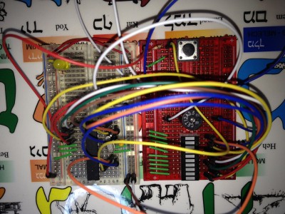 The breadboard setup. You may wonder why there are Hebrew letters on my work surface; that’s because it’s a Hebrew alphabet placemat. I figured that’d be a nice way to very slowly learn something else while I work.[/caption]
The first step was prototyping all the electronics, which I did on a standard solderless breadboard. With a fairly simple circuit like this, it’s not too hard to lay everything out and get it working for the most part before writing the code.
The code and the chip
Writing the code, however, was hard. I’ve never written a substantial program in C before, though fortunately working with Arduino means that I didn’t have to get very deep into actually understanding things like pointers - I could sort of treat C as a scripting language. Here’s the code on GitHub if you’re interested.
However, I still had to think of a reasonable way to control ten LEDs and write a bunch of macros for things like flashing them all at once. I also had to figure out how to play music on a piezo buzzer, which there are libraries out there for, thankfully, e.g. the Arduino Tone library. The project incorporates a button as well, which occasionally was very frustrating to deal with because weak wire connections would cause the button to trigger without being touched.
I used the ATMega328 that ships with the Arduino Uno instead of switching it out for a lower-power or smaller chip. I did actually also spend a couple days trying to get a replacement chip to work, in particular the ATTiny84 (which is smaller and lower-power without having so few pins that I’d need to use a shift register).
But I couldn’t get the Tone library to work with it. I also had some problems with compatibility with the Arduino programming environment, which I’m sure more advanced users wouldn’t have encountered, but which didn’t seem possible for me to solve. It’s also a lot more convenient to upload code to the ATMega328 since it can just be dropped into the Arduino, programmed, and then removed and installed on the breadboard or PCB. The ATMega328 is frankly overpowered for this application, and eventually I’d like to learn to use the right microprocessor for a project instead of the convenient one.
Interesting UX problems
This project posed some very interesting UX problems, which I posted about on Hacker News, and on this blog. I’m so used to working in text and graphics as a medium of expression. What happens when I only have an LED, with two states, to work with? Sure in this case I have ten LEDs, but that doesn’t compare to the limitless pages of text, video, sound or graphics that otherwise have available.
I ultimately decided that (a) all the bars should blink simultaneously while waiting for input, (b) that each bar should represent one minute during the selection and countdown process, and © the bar representing the current minute in a countdown should blink faster as the minute ends. Even with a few LEDs, there were lots of alternative indications I could have used. For example, I could have used a scanning motion, fading in and fading out, or even Morse Code to represent various states. The states I chose for the bar graph also were strangely evocative; both my wife and I felt increasingly anxious as the bars blinked faster toward the end of a minute.
These discoveries led me to a fascinating paper called “Unlocking the Expressivity of Point Lights” which deals with just this issue. In the paper, 24 different single-LED light patterns are identified, such as twinkling, fast pulsing, beacon, and heartbeat behaviors, together with 12 different behaviors such as a low battery state, waiting for user input, or normal operation. The authors then surveyed users to figure out which light pattern was most effective at conveying which state. For notification, for example, it’s two quick blinks (the beacon pattern). For some other states, the data was less conclusive; the best match for “running out of battery” was a flickering candle pattern.
Putting it all together
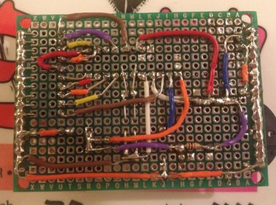 The back of the circuit board. I've used solder bridges a lot, and I also used wire that wasn't always properly insulated. Next time, I'll consider using wire of a thinner gauge as well.[caption id="attachment_2216" align="alignleft" width="400"][/caption]
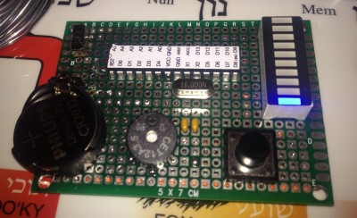 The front of the board. I left the ATMega pinout diagram in place as I needed it to get everything placed correctly.[caption id="attachment_2217" align="alignleft" width="400"][/caption]
Once the code was all written and tested with a breadboard version of the circuit, it was time to assemble everything onto its own circuit board.
What I really wanted to do is make a custom PCB, but this turned out to be really difficult for me. Even programs like Fritzing were not intuitive. So, I ended up buying some cheap protoboard and soldering the connections together myself.
It kind of looks OK for a first try, and it works, which I think is the most important thing. But there are some big improvements that can be made without significantly increasing the cost of building these.
Using smaller-gauge wire, which is easier to work with
Using tools to bend and place the wire instead of bending and placing by hand
I’m considering buying uninsulated wire in particular, and using electrical or other tape to shield it from wires that need to cross the same space.
I also bought a much better soldering iron which seems to be quicker to heat up and therefore less time-consuming to work with. It should also reduce the amount of excess solder I have to use.
Lastly, the timer as currently built has an interesting property, which is that the buzzer only works when the battery is almost completely fresh. The rest of the timer will work just fine after the initial use, but the buzzer just clicks instead of playing a tune.
When I understand better how electronics work, I bet I’ll be able to troubleshoot this more effectively (my guess is that a brand-new battery is just barely able to power all the components, and once the voltage starts dropping, that ability goes away). I’ll probably replace the coin cell battery with a AAA or two. I’d also like to make a case for this timer as well, which I’ll do after my next project is complete.