Building a desktop fabricator (3D Printer), Day 4
January 4, 2011
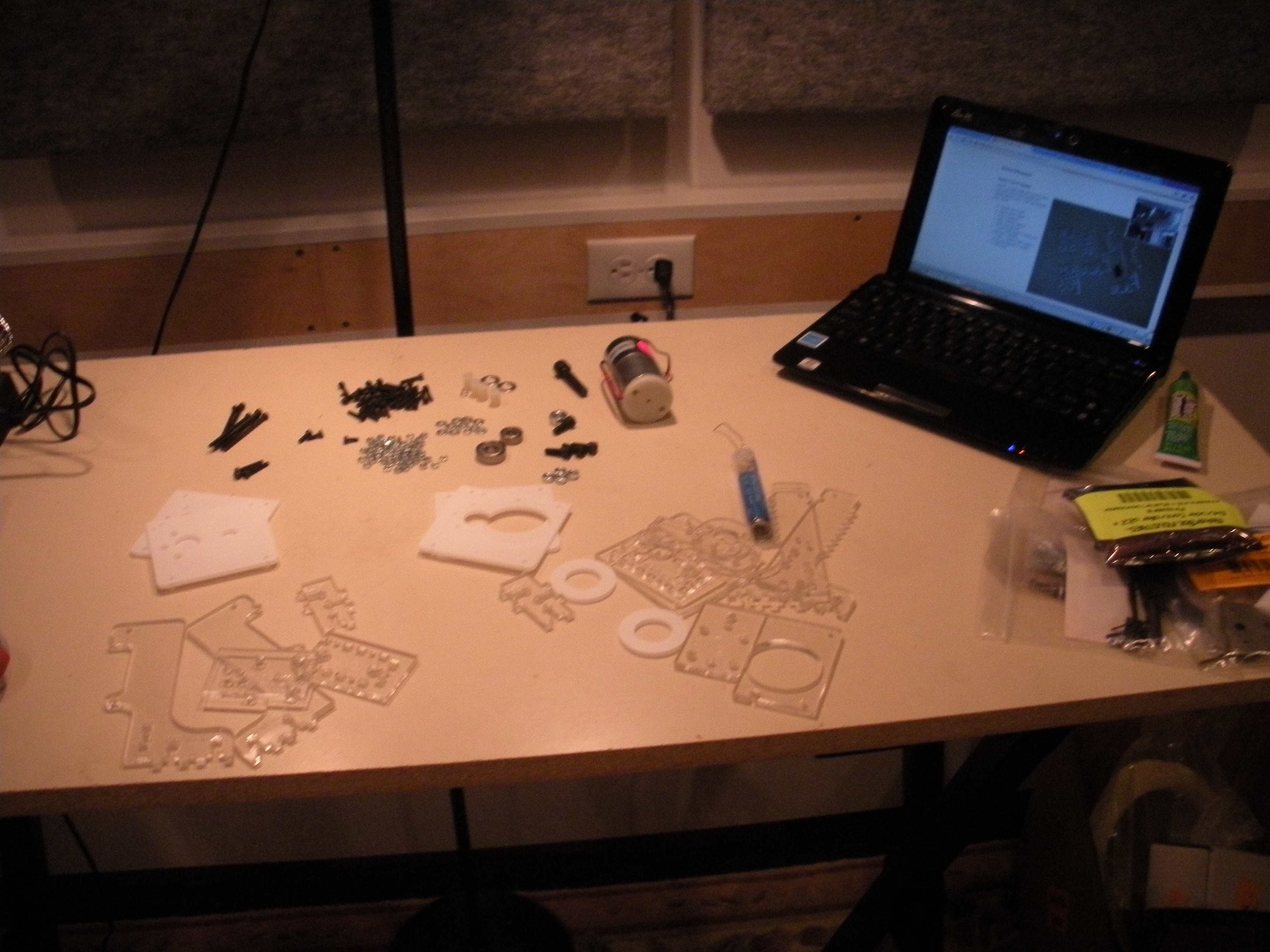 [caption id="attachment_999" align="alignleft" width="300" caption="The setup for building the extruder."][/caption]
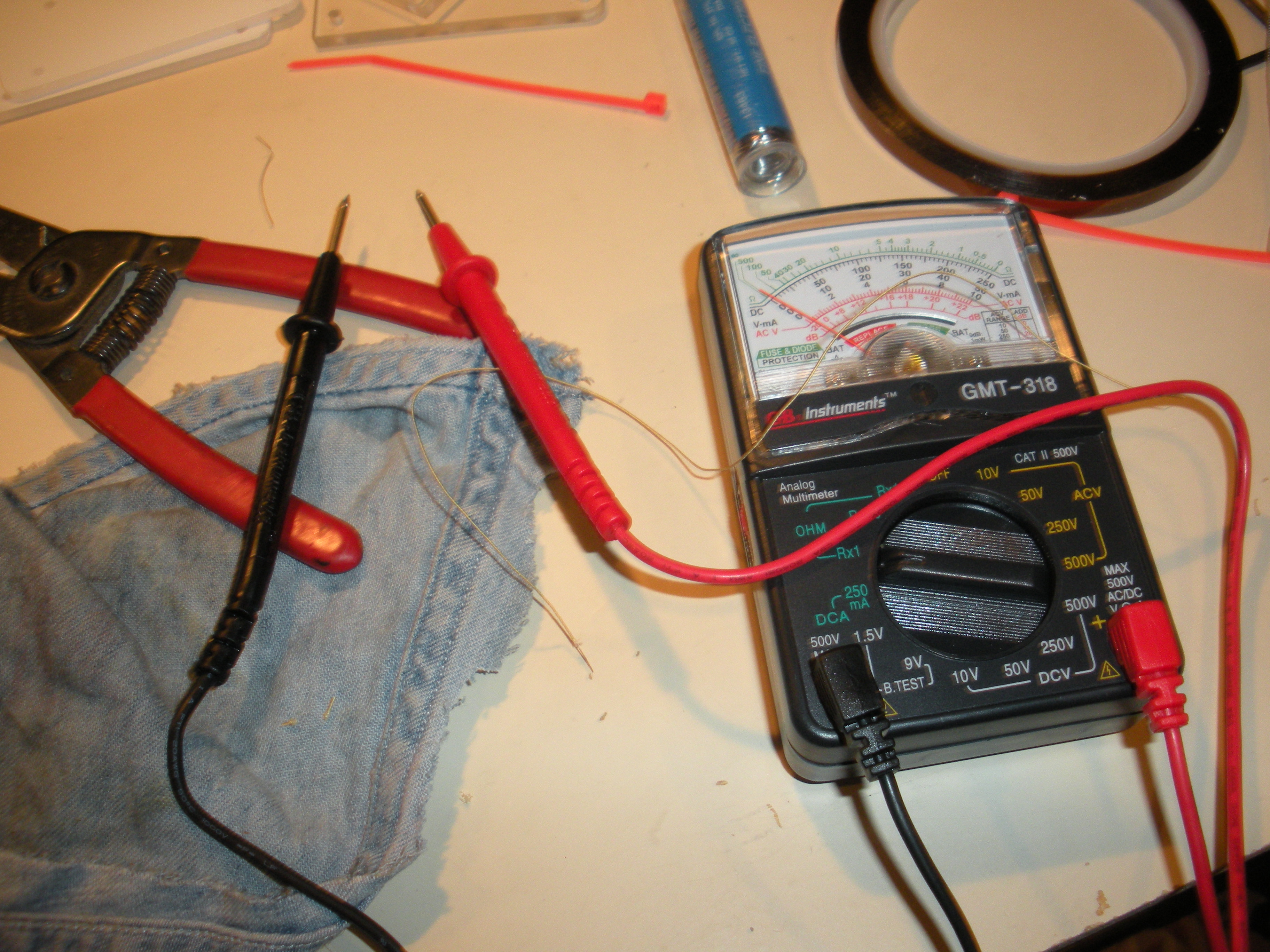 [caption id="attachment_1000" align="alignleft" width="300" caption="The multimeter. The dial on the top measures current flow, the knob allows adjusting the range that the dial shows. The red and black leads connect to an electrical source."][/caption]
_
Note 1: This entry is the fourth in a series.
Note 2: I am looking for likeminded people who want to work together on building some kind of desktop fabricator business. If you read this and agree with what I have to say, will you drop me a note? For more about me, check out my LinkedIn profile.
_ When I left off yesterday, I was about to start building the extruder for my Makerbot. The extruder is the part that heats up, and then lays down, the plastic used as printing material - it’s the 3D printer equivalent of a printer head.
Building the extruder, for an electronics novice like me, is intimidating. This would be first time I’ve ever really soldered, used a multimeter, etc. (A multimeter, by the way, is a device that allows you to measure how much electricity is flowing across a circuit.)
The first step was actually to go shopping! I needed a bunch of stuff that wasn’t included in the kit, such as the multimeter, wire strippers and cutters, and some other odds and ends. I also thought I would need kapton tape, which is a special type of insulating tape that turned out to be included in the kit. Thank goodness for that, since it wasn’t available at any of several electronics stores I tried in Portland. Neither was a certain type of wire that’s called for, which also turned out to be included in the kit… I think.
These slight oversights bring me to one thing that bothered me generally about this part of the build process: it’s a level up in difficulty from the rest of the build, and the instructions provide lower quality, and often less, guidance than before. I think this is one thing that will definitely need to be addressed if the Makerbot is to have wider appeal (or perhaps, as I said yesterday, the extruder should just be pre-built for you). As an example, to quote from the instructions:
The nichrome wire should have a resistance of approximately 6 Ohm. Usually this amounts to about 300 mm of wire, but use a multimeter to be on the safe side. Cut the nichrome wire to a length which amounts to about 6 Ohm of resistance (+/- 1 Ohm). NOTE: It's difficult to measure the resistance of the nichrome until you strip the ends, so cut it long, then trim it down until you reach 6 Ohms. NOTE: Make the wire too long, and your heater takes longer to heat up. Make it too short, and you burn out the MOSFET on the extruder board.
So, what does this mean? You have to cut a certain type of wire to a certain length. In order to get the right length, you have to measure the resistance with a multimeter. If you haven’t used a multimeter before, you have to learn how to do so. And then if you get it wrong, you may end up destroying a critical component of the machine when you start to use it.
Fortunately, learning to use a multimeter isn’t that hard, and I was able to figure it out. So what am I complaining about? I guess I don’t really mean to complain - this kit is clearly targeted at hobbyists, and as I’ve said many times, it’s an ingenious machine and up to now extremely thoughtfully documented. But I think it would be a good idea to simplify build process steps such as this one, and that will be necessary to broaden the appeal of these fabs beyond hobbyists.
There are some other really touchy steps, too - for example, when building the idler wheel, you have to put a circular bearing within a larger plastic ring. But the bearing must be glued to the outer wheel at a very precise depth - i.e. it shouldn’t be flush with either the top or the bottom of the wheel. Moreover, it has to be superglued in place, so, no second chances. Lastly, there is some kind of problem with the instructions here, where someone has inserted a note to update the instructions, without actually doing this. I had to tread carefully, and I’m not 100% sure that I did it right.
[caption id=“attachment_1001” align=“alignleft” width=“300” caption=“A soldered (and then taped) wire connection.”]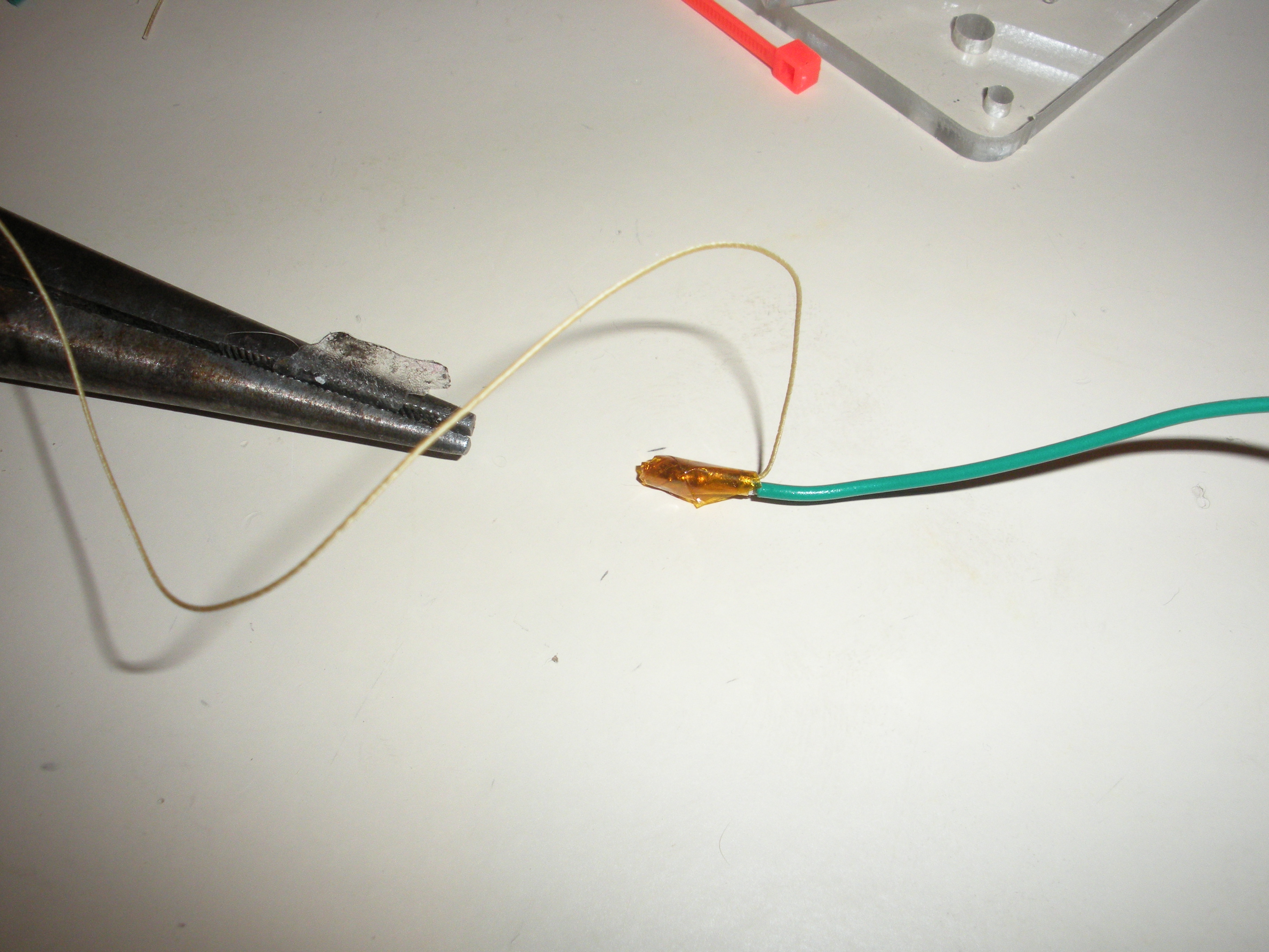 [/caption]
Things like this aside, construction actually went pretty well. I did my first real soldering - hooray! - and you can see the results of that in the pictures accompanying this post. Tomorrow, I’ll try to get a picture of me actually performing the soldering operation, so anyone unfamiliar can see what that actually looks like. This was a pretty forgiving situation, but I was happy that that went well, and I was able to confirm that everything was OK, using the multimeter (which is a very cool tool).
I also built the supports for the extruder, which are called “Weird Dinosaur” and “Big Dinosaur” on account of their shapes. I’m not sure if this is helpful nomenclature or not…
Tomorrow I am hoping to complete the build of the Makerbot, though there’s a lot to do between now and then.